C language implementation of I2C slave mode using PIC16F1825

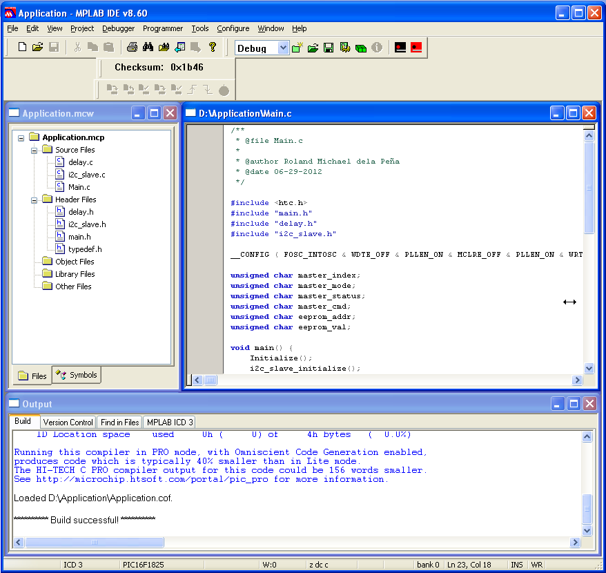
This article shows an implementation of I2C slave mode using PIC16F1825 written in C language and how to test or simulate the codes in PICkit Serial Analyzer I2C software (Note: Hardware part will not be shown here).  There's a detailed discussion of I2C slave mode that can be found at Microchip Application Note 734.  However, the sample code in this Application Note is written in assembly language.

Basically, it consist of three source files and their counterpart header file:

Main.c main.h

#include <htc.h>
#include "main.h"
#include "delay.h"
#include "i2c_slave.h"
__CONFIG ( FOSC_INTOSC & WDTE_OFF & PLLEN_ON & MCLRE_OFF & PLLEN_ON & WRT_OFF) ;
unsigned char master_index;
unsigned char master_mode;
unsigned char master_status;
unsigned char master_cmd;
unsigned char eeprom_addr;
unsigned char eeprom_val;
void main() {
Initialize();
i2c_slave_initialize();
while (1) {
process_i2c_tasks();
} // end of while (1)
}
void Initialize () {
OSCCON = 0xFA;
}


void Initialize ();

i2c_slave.c i2c_slave.h

#include <htc.h>
#include "i2c_slave.h"
#include "delay.h"
const unsigned char mask = 0x25; //I2C states mask
void i2c_slave_initialize() {
TRIS_SDA = 1; // SDA input
TRIS_SCL = 1; // SCL input
SSPBUF = 0x0;
SSPSTAT = 0x80; // 100Khz
SSPADD = SLAVE_ADDR;
SSPCON = 0x36; // Slave mode, 7bit addr
SSPCON3 |= 0b01100000; // enable start and stop conditions
}
void _write_data(unsigned char data) {
do {
WCOL=0;
SSPBUF = data;
} while(WCOL);
CKP = 1;
}
int process_i2c_tasks() {
unsigned char temp;
unsigned char token = 0;
if (SSP1IF) {
token = SSPSTAT & mask; //obtain current state
if (S) {
switch (token) {
case MWA: //MASTER WRITES ADDRESS STATE
temp = SSPBUF;
master_status = I2C_SLAVE_ADDRESS_RECEIVED;
break;
case MWD: //MASTER WRITES DATA STATE
temp = SSPBUF;
if (master_status == I2C_SLAVE_ADDRESS_RECEIVED) {
// first time we get the slave address, after that set to word address
master_mode = temp;
master_index = 0;
master_status = I2C_MODE_RECEIVED;
}
else if (master_status == I2C_MODE_RECEIVED) {
// second time we get the mode, so look into mode
if (master_mode == MODE_WRITE_EEPROM) {
++master_index;
if (master_index == 1) {
// We've got the EEPROM address
eeprom_addr = temp;
}
else if (master_index == 2) {
// We've got the assigned EEPROM value
eeprom_val = temp;
master_cmd = EXECUTE_WRITE_EEPROM;
}
else if (master_index > 2) {
master_cmd = EXECUTE_NONE;
}
}
else if (master_mode == MODE_READ_EEPROM) {
// We've got the EEPROM address
eeprom_addr = temp;
master_cmd = EXECUTE_READ_EEPROM;
}
else if (master_mode == MODE_RESET) {
master_cmd = EXECUTE_RESET;
}
}
break;
case MRA: //MASTER READS ADDRESS STATE
temp = SSPBUF;
if (master_cmd == EXECUTE_READ_EEPROM) {
_write_data(eeprom_read(eeprom_addr));
}
break;
case MRD: //MASTER READS DATA STATE
break;
}
}
else if (P) { //STOP state
asm("nop");
if (master_cmd == EXECUTE_WRITE_EEPROM) {
eeprom_write(eeprom_addr, eeprom_val);
}
else if (master_cmd == EXECUTE_RESET) {
DelayMs(5);
#asm
RESET;
#endasm
}
master_status = I2C_NO_TRANSACTION;
}
SSP1IF = 0;
SSPEN = 1;
CKP = 1; //release clock
}
}


#include "typedef.h"
#define TRIS_SDA TRISC1
#define TRIS_SCL TRISC0
// Serial communication states
#define I2C_NO_TRANSACTION 0
#define I2C_SLAVE_ADDRESS_RECEIVED 1
#define I2C_MODE_RECEIVED 2
#define I2C_READ_ADDRESS 3
#define I2C_READ_DATA 4
#define I2C_MASTER_NACK 5
#define MODE_WRITE_EEPROM 0xaa
#define MODE_READ_EEPROM 0xab
#define MODE_RESET 0xac
// DSADS01 defined execute command
#define EXECUTE_NONE 0xa0
#define EXECUTE_WRITE_EEPROM 0xa1
#define EXECUTE_READ_EEPROM 0xa2
#define EXECUTE_RESET 0xa3
// slave address definition
#define SLAVE_ADDR 0xa0
// define states
#define MWA 0x1 //Master Writes Address
#define MWD 0x21 //Master Writes Data
#define MRA 0x5 //Master Reads Address
#define MRD 0x24 //Master Reads Data
// function prototypes
void i2c_slave_initialize(void);
int process_i2c_tasks(void);
extern unsigned char master_index;
extern unsigned char master_mode;
extern unsigned char master_status;
extern unsigned char master_cmd;
extern unsigned char eeprom_addr;
extern unsigned char eeprom_val;

delay.c delay.h

#include "delay.h"
void DelayMs(unsigned char cnt) {
#if XTAL_FREQ <= 2MHZ
do {
DelayUs(996);
} while(--cnt);
#endif
#if XTAL_FREQ > 2MHZ
unsigned char i;
do {
i = 4;
do {
DelayUs(250);
} while(--i);
} while(--cnt);
#endif
}

Note that this is the crystal frequency, the CPU clock is divided by 4.

#ifndef XTAL_FREQ
#define XTAL_FREQ 8MHZ /* Crystal frequency in MHz */
#endif
#define MHZ *1000L /* number of kHz in a MHz */
#define KHZ *1 /* number of kHz in a kHz */
#if XTAL_FREQ >= 12MHZ
#define DelayUs(x) { unsigned char _dcnt; \
_dcnt = (x)*((XTAL_FREQ)/(12MHZ)); \
while(--_dcnt != 0) \
continue; }
#else
#define DelayUs(x) { unsigned char _dcnt; \
_dcnt = (x)/((12MHZ)/(XTAL_FREQ))|1; \
while(--_dcnt != 0) \
continue; }
#endif
extern void DelayMs(unsigned char);

There is an attachment file available for download below that contains the source codes and MPLAB project setup of this application.

Here are the steps simulating the I2C application on PICkit Serial Analyzer software:

This test will demonstrate writing and reading functionality.

  1. First of all, compile the I2C application using MPLAB.
    I2C application compiled using MPLAB
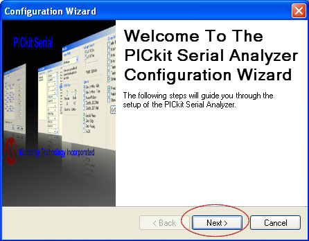
  2. Connect your hardware to PICkit Serial Analyzer cable. Open PICkit Serial Analyzer and click "Next" button.
    PICkit Serial Analyzer Step 1
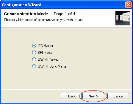
  3. Select "I2C Master" and click "Next" button.
    PICkit Serial Analyzer Step 2
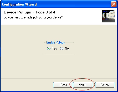
  4. Select "Yes" and click "Next" button.
    PICkit Serial Analyzer Step 4
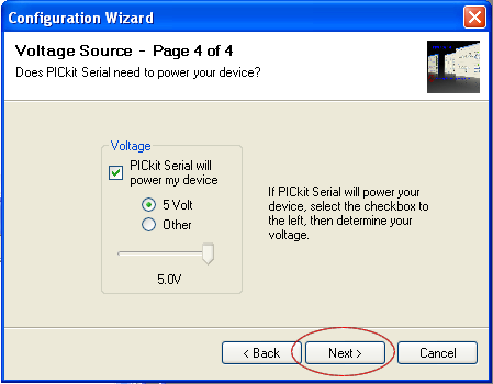
  5. Make sure the "PICkit Serial will power my device" is checked and "5 Volt" is selected then click "Next" button.
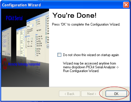
    PICkit Serial Analyzer Step 5
  6. Click "OK" button.
    PICkit Serial Analyzer Step 6
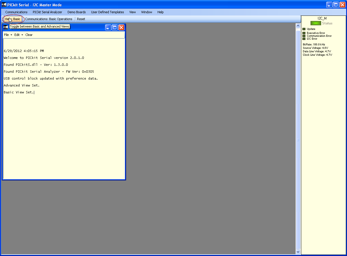
  7. Click "View: Basic" at top left.
    PICkit Serial Analyzer Step 7
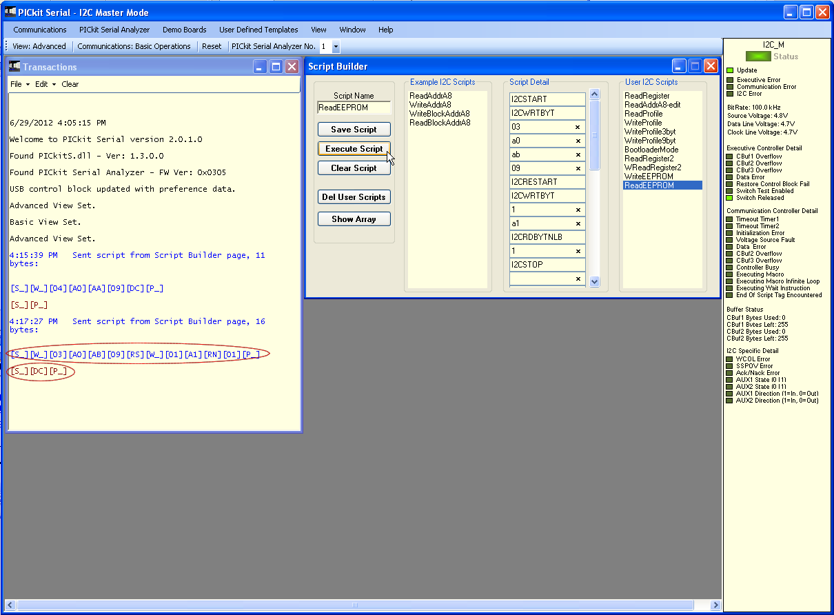
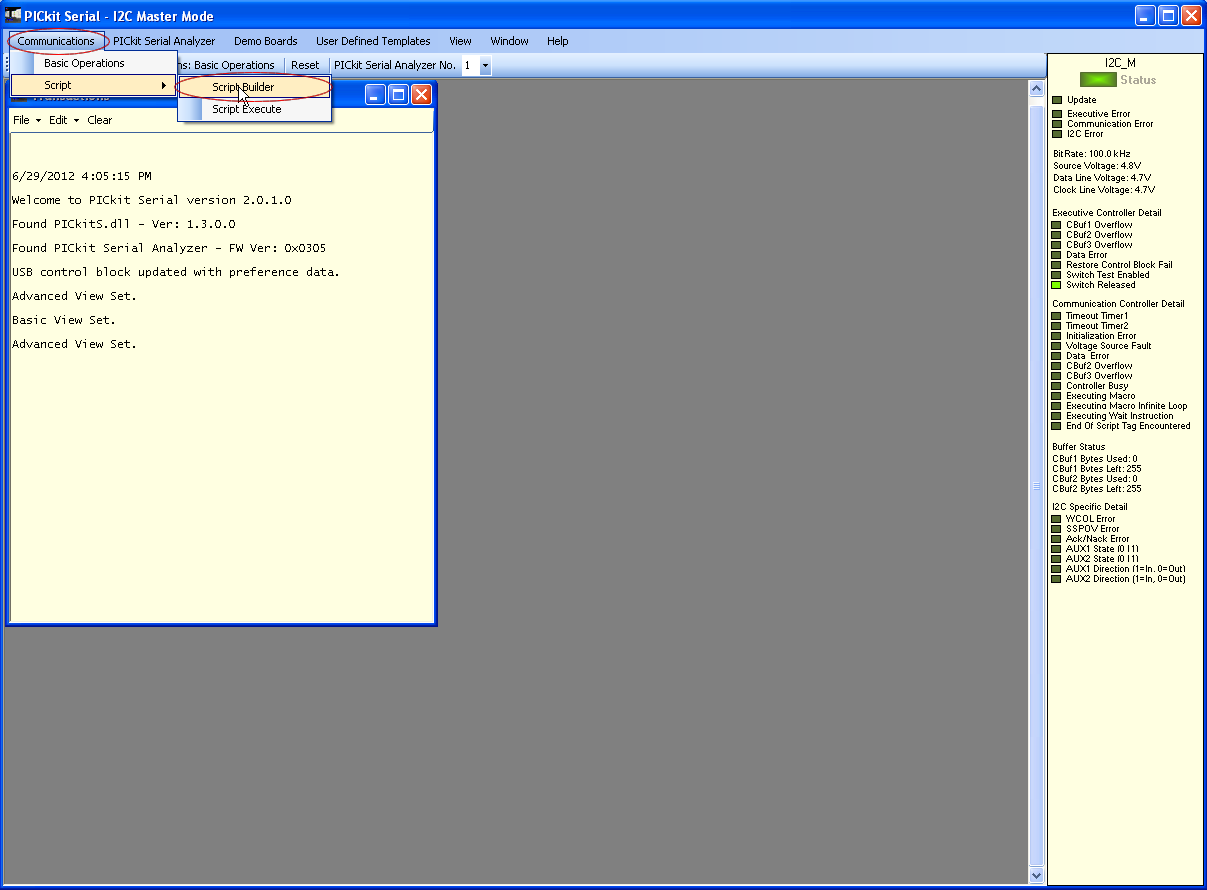
  8. Form menu bar, select "Communication" and click "Script Builder".
    PICkit Serial Analyzer Step 8
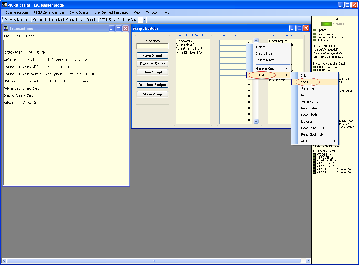
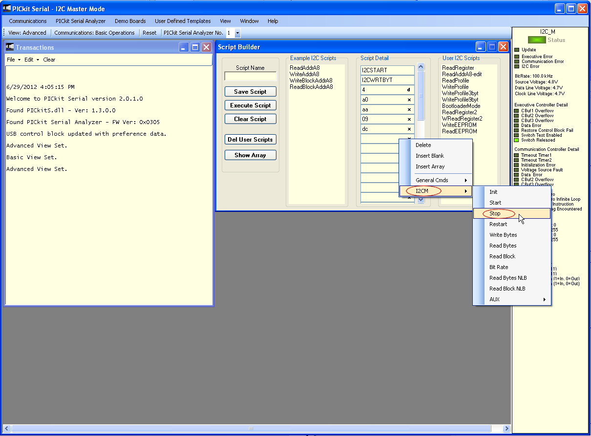
  9. We will create script for "Write" function. On "Script Builder" window under "Script Detail", select I2CM and click "Start" (this represents the start bit in I2C protocol).
    PICkit Serial Analyzer Step 9
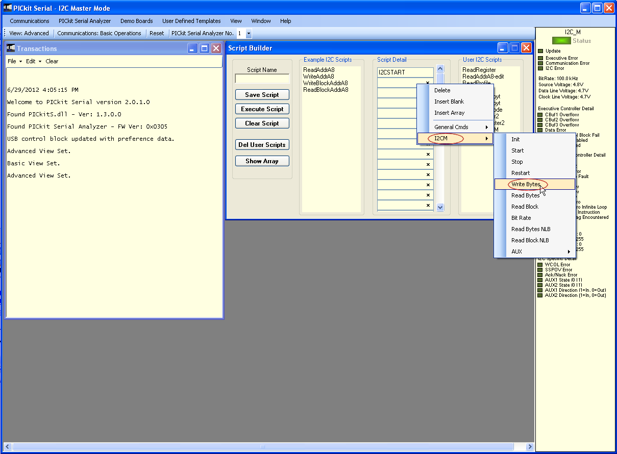
  10. Next we'll setup the write byte. On "Script Builder" window under "Script Detail", select I2CM and click "Write Bytes".
    PICkit Serial Analyzer Step 10
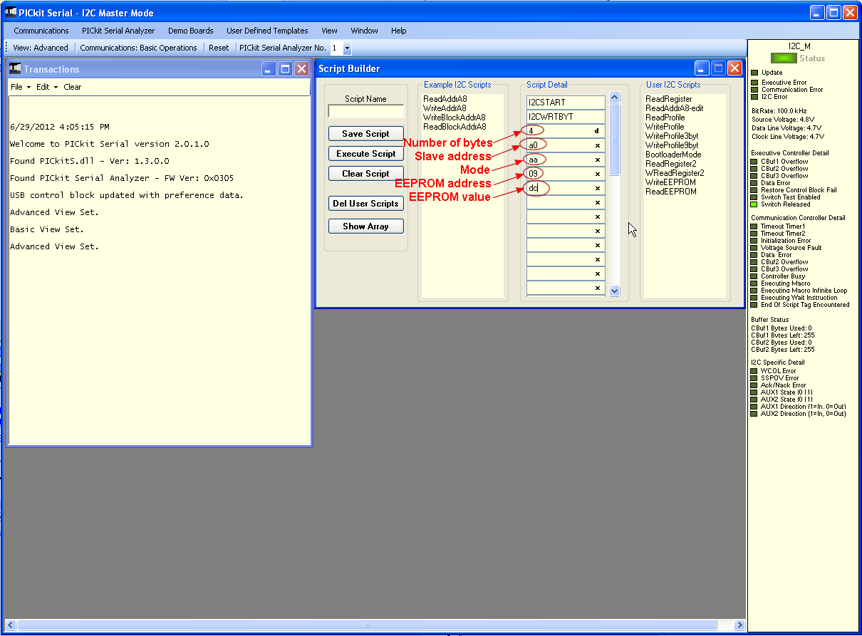
  11. We will enter next the number of bytes and it is good to format it as decimal to avoid mistakes. On "Script Builder" window under "Script Detail" third row, click the "x" to switch to "d" (this means decimal and "x" means hexadecimal).
    PICkit Serial Analyzer Step 11
  12. Next enter the rest of data: slave address, mode, EEPROM address and EEPROM value on "Script Builder" window under "Script Detail" on rows available.
    PICkit Serial Analyzer Step 12
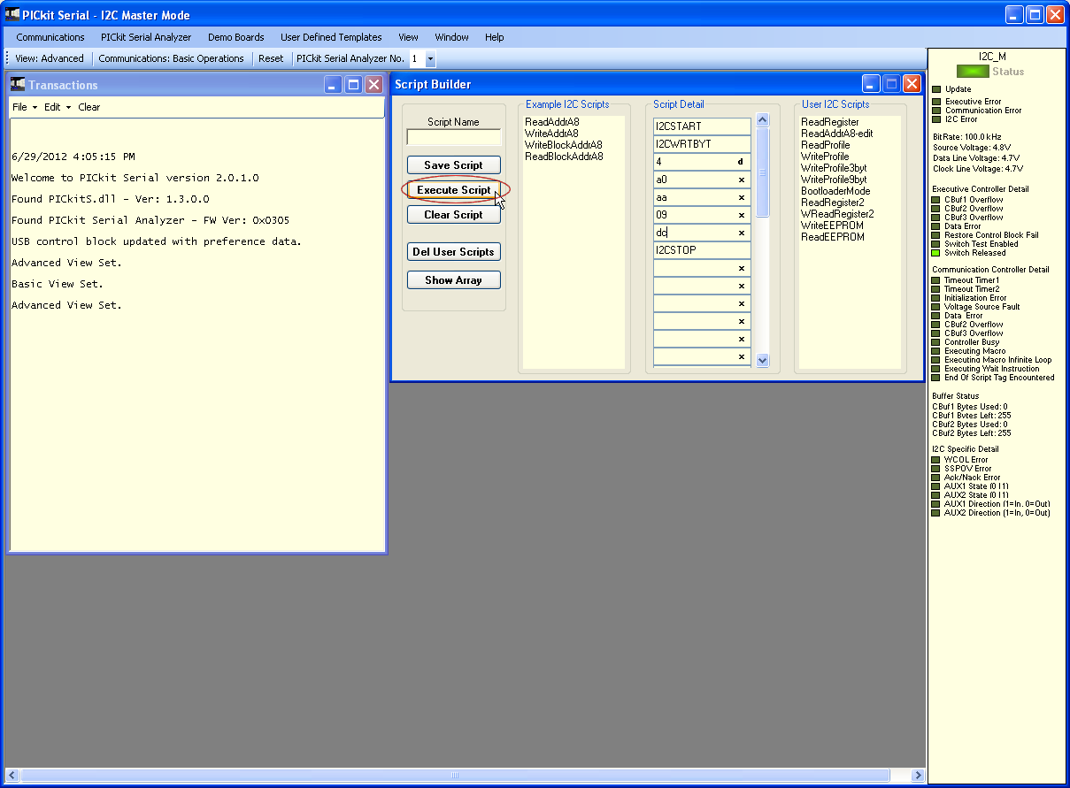
  13. Add the stop bit on available row of "Script Builder" window under "Script Detail".
    PICkit Serial Analyzer Step 13
  14. Click "Execute Script" button.
    PICkit Serial Analyzer Step 14
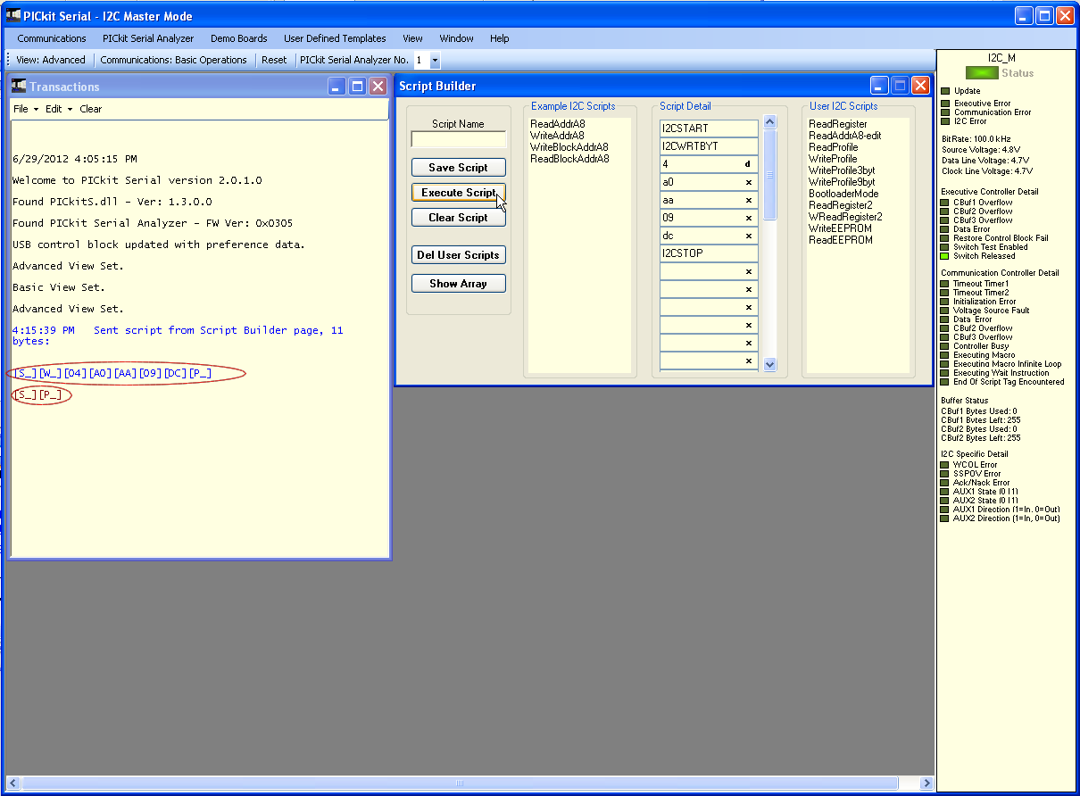
  15. The "Transaction" window will display the data sent to and received from the PIC16F1825 microcontroller. The text in blue font color represent the host or PC and text in red font color represent the microcontroller.
    PICkit Serial Analyzer Step 15
  16. I have already created script for the "Read" function named "ReadEEPROM". Just copy the data shown at "Script Builder" window under "Script Detail".
    PICkit Serial Analyzer Step 16
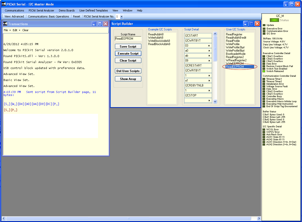
  17. After creating the "Read" function script, click "Execute Script" button.
    PICkit Serial Analyzer Step 17
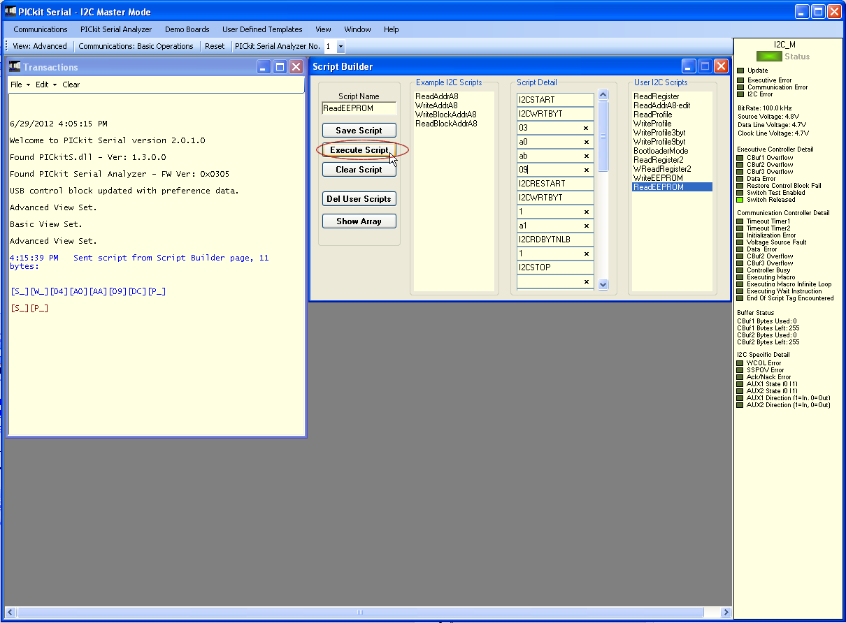
  18. The "Transaction" window will display the data sent to and reply from the PIC16F1825 microcontroller.
    PICkit Serial Analyzer Step 18

Add new comment

Restricted HTML

  • Allowed HTML tags: <a href hreflang> <em> <strong> <cite> <blockquote cite> <code> <ul type> <ol start type> <li> <dl> <dt> <dd> <h2 id> <h3 id> <h4 id> <h5 id> <h6 id>
  • Lines and paragraphs break automatically.